
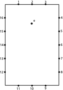
16 wall nodes and one emitter.
1st order reflections
* For each wall node (1-16) calculate the distance between e and the node expressed in time (sample frames).
* For each wall node (1-16) calculate the level attenuated by the nodes absorption coefficient.
* For each wall node (1-16) calculate the angle of incidence.
1st order rendering
* For each wall node (1-16) calculate the distance between receptor and the node expressed in time (sample frames).
* For each wall node (1-16) compare the stored angle of incidence with the receptors angle of incidence. If equal then record the response with the nodes stored level at summed time.
2nd order reflections
Is calculated the same way as the 1st order rendering but with each node acting as a receptor and the stored 1st order values and nodes are used as emitters.
2nd order rendering
Is calculated just like the 1st order rendering but using the result of the 2nd order reflection step instead of the 1st.
Of course, if a receptor don't have a free line-of-sight to an emitter (or nodes acting as receptor/emitters), for example they belong to the same wall, that pair shouldn't be calculated.
All the reflection steps (1st, 2nd and so on) are calculated first then the final impulse is rendered using them as input, so that the result of the reflection steps can be reused to render multi-channel impulses. I just interleaved the steps to make the explanation clearer (I hope!).
Is this completely bonkers?

